Outside Plant Infrastructure Editor
 Outside Plant Infrastructure Editor
Outside Plant Infrastructure Editor training requires civil experience and an understanding of the outside plant infrastructure, ITS devices, and cabinet equipment supporting ITS installation. This editor training is conducted on a one-to-one basis using video teleconferencing sessions with the student and instructor and is performed using actual as-built data and encoded directly in the production system under the supervision of the instructor. Students learn an encoding task, then perform that task throughout the project limits until complete. The instructor audits the work for accuracy and completeness, then advances the student to the next encoding task.
Class Duration
- The training time frame can take several weeks to months based on the student’s previous experience and the project limits.
Prerequisites
- Previous civil or outside plant telecommunication experience.
- Advanced level computer experience.
- ITSFM Maintainer certificate of completion.
- Must have a four to eight-week backlog of data available for encoding new or updating existing features in the production system.
Hardware/Software Requirements
- Computer equipped with Internet Explorer or Chrome web browser, Skype, Trimble Pathfinder Office (non-licensed viewer), MS Excel, and Google Earth.
- Dual monitors are recommended.
Laptop Configuration Requirements
- Students MUST verify their laptop computer is properly setup and configuration using the “Job Aid for Testing ITSFM System Config,” found in the “Resource” tab in Learning Curve.
- Internet access.
Syllabus
Step 1 – Bulk import cleanup:
- Improve the visibility of ITS features that share the same coordinate values. Features are moved slightly in the map view to minimize congestion with hidden or stacked features.
Step 2 – Duct bank makeup:
- Populate each conduit duct bank with the conduit length, quantity, type, usage, and spare conduit quantity.
Step 3 – Create fiber optic cables:
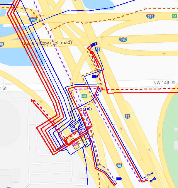
- Fiber cables will be schematically drawn and placed adjacent and parallel to the underground conduit duct bank or aerial pole line housing the cable. The cable placement will provide clarity and ease of tracking.
- The cable length and cable slack lengths will be derived from the fiber optic cable schematic drawing furnished by the data collector.
Step 4 – Place data, video, composite, and electric cables.
Step 5 – Populate electrical system:
- Electric site attributes.
- Create electrical distribution circuits and associate to the electric cables, electric sites, and ITS equipment cabinets.
Step 6 – Build feature associations:
- Feature association is created to enable system reporting and configuration management.
Step 7 – Attach photos and as-built plans:
- Cabinet photo and as-built plan sheet will be attached to the appropriate ITS features.
Step 8 – Perform operational test:
- Numerous tests will be performed to verify that minimum feature attribution was met, locates and standard reports are reporting as expected, and there are no cable length or slack loop errors generated when using the fiber trace tool.
